SIMATIC S5 S5-115U Programmable Controller Manual CPU 941-7UB11 CPU 942-7UB11 CPU 943-7UB11 and CPU 943-7UB21 CPU 944-7UB11 and CPU 944-7UB21 EWA 4NEB 811 6130-02b. It is so important for PLC programmers not only to know about PLC programming, but also to know about electronics and hardware. Because of how the hardware works it can generate errors both at the inputs and at the outputs of a PLC. Most modern PLC's has a build-in filter on the input side to avoid noise and bouncing. S Contents Preface 1 Guide to the S7-300 Documentation 2 Installation Order 3 S7-300 Modules 4 Configuring 5 Installation 6 Wiring 7 Addressing 8 Commissioning 9. Here it uses Allen Bradley notation for PLC-5 racks. At the top is the location of the input card I:013 which indicates that the card is an Input card in rack 01 in slot 3.
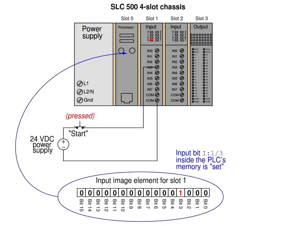
There are a number of addressing schemes used by PLC manufacturers. Let's take a quick look at how memory locations (including hardware I/O) are accessed with RSLogix 500. Along the way, let's define some terms.
INSTRUCTION – RSLogix's command language is comprised of 'instructions'. An XIC (it looks like a normally open contact –] [– ) is an instruction. A timer is an instruction. A few of the most common instructions are described below.
BIT – an address within the PLC. It can be an input, output or internal coil, among others.
In RSLogix, there are a couple of ways to show the address of a bit. The default is:
[type]:[word]/[bit]
For example, an address that references an output of a MicroLogix 1100 is O:0/0. That is:
O:0/5 means that it is a physical output.
O:0/5 means that it uses Slot 0 (in the case of the 1100, this output is onboard)
O:0/5 means that it is the fifth output on the PLC.
By the way, don't get the capital 'O' confused with a zero.
RUNG – A section of the PLC ladder program that terminates in an output function of some type. Just like in an electrical ladder diagram, a rung has some type of output that is turned on or turned off by the preceding entities in the rung. The first rung in a ladder program is always 0000.
HARDWIRED INPUT – a physical connection to the PLC from an input device (switch or sensor, etc.).
Allen-Bradley uses the capital letter 'I' to designate a hardwired input. An address that describes an input on an SLC 500 is I:4/0.
Plc 5 1/2 Slot Addressing System
Similar to the output structure,
I:4/0 means that it is a physical input.
I:4/0 means that it uses Slot 4 (the 5th slot in the rack).
I:4/0 means that it is the first input on the card.
Don't get the capital 'I's' confused with ones.

HARDWIRED OUTPUT – a physical connection from the PLC to an output device (relay or pilot light, etc.) As was said above, an address that references an output of an SLC 500 is O:5/0.
INTERNAL COIL
This is a programmable bit used to simulate a relay within the PLC. The internal coil has no connection to the outside world. It does not connect to an output card. Internal coils are used to store information. The 'contacts' of this 'relay' can then be used multiple times in other parts of the program.
In RSLogix, the 'B3' (binary) file is commonly used for all the internal coils. There are many other words in other files that have bits you can use as internal coils, but we are going to stick with the B3 file for our application.
B3:0/0 means that it references an internal Binary file
B3:0/0 means that it uses the first word in the table
B3:0/0 means that it is the first bit in the word.
Note that, unlike the Output and Input files, you have to use the file number in the address. In this case, the default file number is 3.
TIMER
A timer is a programmable instruction that lets you turn on or turn off bits after a preset time.
The two primary types of timers are TON for 'timer on delay' and TOF for 'timer off delay'.
Timers in A-B SLC and MicroLogix processors use file 4 for their timers.
T4:0 means that it references an internal Timer file
T4:0 means that it uses the first timer in the table

The address T4:0 simply refers to the timer. Each timer has bits that turn on after the timing function is complete. You can address this bit by simply putting a '/DN' after the timer address. DN stands for 'done'.
For example, if timer T4:0 is a TON (timer on delay), then the bit T4:0/DN will turn on after the timer has reached its preset value.
COUNTER
A counter is a programmable instruction that lets you turn on or turn off bits after a preset count has been reached.
Total life earnings: $2,030,694. Latest cash: $2,649 on 26-Aug-2020. Click here to see the details of Ognjen Sekularac's 82 cashes. Ognjen Sekularac poker results, stats, photos, videos, news, magazine columns, blogs, Twitter, and more. Paul Seaton - June 7, 2019 With another packed day of action at the felt complete, Day #9 was one of the busiest days yet at the 50th annual World Series of Poker. From big bracelet wins for two players who didn't have one until now to a rollercoaster ride in the Big 50, we've taken a look back at what All Ognjen Sekularac articles.
There are different types of counters available in the RSLogix, but the CTU (counter up) instruction covers everything we will talk about here.
Counters in A-B SLC and MicroLogix processors use file 5.
C5:0 means that it references an internal Counter file
C5:0 means that it uses the first counter in the table
The address C5:0 simply refers to the counter. Each counter has bits that turn on after the counting function is complete. You can address this bit by simply putting a '/DN' after the counter address. DN stands for 'done'.

For example, if counter C5:0 is a CTU (counter up), then the bit C5:0/DN will turn on after the counter has reached its preset value.

–] [– Normally Open Contact
When used with a hardwired input, this instruction is off until there is a voltage applied to the input. The bit address then goes high, or on, and the instruction becomes 'true.' It works the same way when it has the same address as an internal coil, except that the coil must be turned on by logic in the program.
Allen-Bradley calls these normally open contacts 'XIC', or 'eXamine If Closed' instruction.
An XIC instruction can reference a hardwired input, a hardwired output, an internal coil or a timer done bit, among others.
–]/[– Normally Closed Contact
This is an inverted normally open contact.
When used with a hardwired input, this instruction is 'true' until there is a voltage applied to the input. It then goes low, or off, and becomes 'false.'
It also can be used with an internal coil, becoming true when the coil is off and becoming false when the coil is on.
Allen-Bradley calls these normally closed contacts 'XIO', or 'eXamine If Open' instructions.
Plc 5 1/2 Slot Addressing Machine
-( )- Output Coil
When used with a hardwired output, this function is off until the logic in the program allows it to turn on. It then becomes 'true', and will energize the device that is wired to the respective output.
If it is used as an internal coil, it will toggle the instructions associated with it. That is, it will close a normally open instruction and open a normally closed instruction.
Allen-Bradley calls these outputs 'OTE', or 'OutpuT Energize'.
An OTE may be used with a hardwired output or an internal coil.
TRUE – A state that indicates an instruction is allowing logic to 'flow' through it.
Also, if the logic in a rung turns on the output of the rung, then the rung is said to be true.

HARDWIRED OUTPUT – a physical connection from the PLC to an output device (relay or pilot light, etc.) As was said above, an address that references an output of an SLC 500 is O:5/0.
INTERNAL COIL
This is a programmable bit used to simulate a relay within the PLC. The internal coil has no connection to the outside world. It does not connect to an output card. Internal coils are used to store information. The 'contacts' of this 'relay' can then be used multiple times in other parts of the program.
In RSLogix, the 'B3' (binary) file is commonly used for all the internal coils. There are many other words in other files that have bits you can use as internal coils, but we are going to stick with the B3 file for our application.
B3:0/0 means that it references an internal Binary file
B3:0/0 means that it uses the first word in the table
B3:0/0 means that it is the first bit in the word.
Note that, unlike the Output and Input files, you have to use the file number in the address. In this case, the default file number is 3.
TIMER
A timer is a programmable instruction that lets you turn on or turn off bits after a preset time.
The two primary types of timers are TON for 'timer on delay' and TOF for 'timer off delay'.
Timers in A-B SLC and MicroLogix processors use file 4 for their timers.
T4:0 means that it references an internal Timer file
T4:0 means that it uses the first timer in the table
The address T4:0 simply refers to the timer. Each timer has bits that turn on after the timing function is complete. You can address this bit by simply putting a '/DN' after the timer address. DN stands for 'done'.
For example, if timer T4:0 is a TON (timer on delay), then the bit T4:0/DN will turn on after the timer has reached its preset value.
COUNTER
A counter is a programmable instruction that lets you turn on or turn off bits after a preset count has been reached.
Total life earnings: $2,030,694. Latest cash: $2,649 on 26-Aug-2020. Click here to see the details of Ognjen Sekularac's 82 cashes. Ognjen Sekularac poker results, stats, photos, videos, news, magazine columns, blogs, Twitter, and more. Paul Seaton - June 7, 2019 With another packed day of action at the felt complete, Day #9 was one of the busiest days yet at the 50th annual World Series of Poker. From big bracelet wins for two players who didn't have one until now to a rollercoaster ride in the Big 50, we've taken a look back at what All Ognjen Sekularac articles.
There are different types of counters available in the RSLogix, but the CTU (counter up) instruction covers everything we will talk about here.
Counters in A-B SLC and MicroLogix processors use file 5.
C5:0 means that it references an internal Counter file
C5:0 means that it uses the first counter in the table
The address C5:0 simply refers to the counter. Each counter has bits that turn on after the counting function is complete. You can address this bit by simply putting a '/DN' after the counter address. DN stands for 'done'.
For example, if counter C5:0 is a CTU (counter up), then the bit C5:0/DN will turn on after the counter has reached its preset value.
–] [– Normally Open Contact
When used with a hardwired input, this instruction is off until there is a voltage applied to the input. The bit address then goes high, or on, and the instruction becomes 'true.' It works the same way when it has the same address as an internal coil, except that the coil must be turned on by logic in the program.
Allen-Bradley calls these normally open contacts 'XIC', or 'eXamine If Closed' instruction.
An XIC instruction can reference a hardwired input, a hardwired output, an internal coil or a timer done bit, among others.
–]/[– Normally Closed Contact
This is an inverted normally open contact.
When used with a hardwired input, this instruction is 'true' until there is a voltage applied to the input. It then goes low, or off, and becomes 'false.'
It also can be used with an internal coil, becoming true when the coil is off and becoming false when the coil is on.
Allen-Bradley calls these normally closed contacts 'XIO', or 'eXamine If Open' instructions.
Plc 5 1/2 Slot Addressing Machine
-( )- Output Coil
When used with a hardwired output, this function is off until the logic in the program allows it to turn on. It then becomes 'true', and will energize the device that is wired to the respective output.
If it is used as an internal coil, it will toggle the instructions associated with it. That is, it will close a normally open instruction and open a normally closed instruction.
Allen-Bradley calls these outputs 'OTE', or 'OutpuT Energize'.
An OTE may be used with a hardwired output or an internal coil.
TRUE – A state that indicates an instruction is allowing logic to 'flow' through it.
Also, if the logic in a rung turns on the output of the rung, then the rung is said to be true.
FALSE – Without stating the obvious, this is the opposite of true.
Plc 5 1/2 Slot Addressing Tool
Excerpted from PLC Programming with RSLogix 500